Color-Tunable Elastic Fibers
July 23, 2015
Many scientific designs are inspired by nature. The beautiful blue-green berry hull from the Margaritaria nobilis (bastard hogberry) induced enough curiosity in one research group of scientists to find out what caused its hue. Their findings led to the development of a new fiber—one that changes color when stretched!1
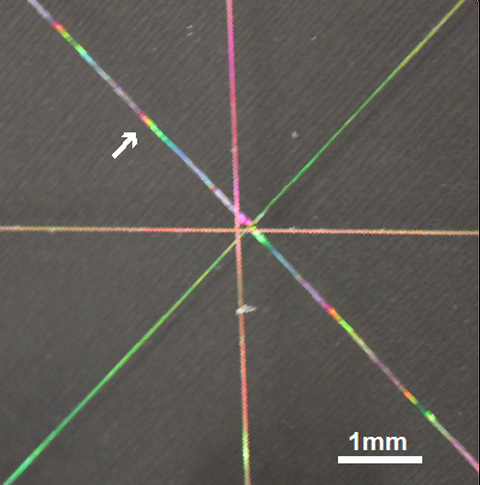
Tunable elastic fibers.
Image credit: Mathias Kolle, Laboratory for Bio-inspired Photonic Engineering (LBPE)
Nature and Blue
Blue pigments and dyes are not common in nature. The minerals lapis and cobalt were long used as pigments, and woad and indigo—which both get their color from the same molecule—were used as dyes. Pigment and dye both work by absorbing certain colors of light, so we see the color of light left over. However, most biological blues—bird feathers, wings of insects, blue-rayed limpets, and some fruit—create their blue appearance not by selective absorption and reflection, but by employing structural techniques.
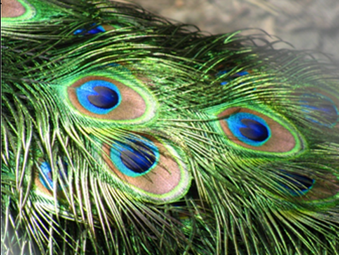
A peacock's tail displays flashy colors and hypnotic patterns. Illuminated from behind, however, the feathers appear a rather plain brown color. Read on to find out why!
Image Credit: "Peacock Feather" by user:AlexDuarte - Own work. Licensed under Public Domain via Wikimedia Commons
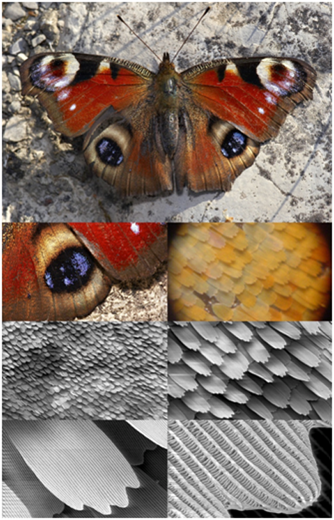
A peacock butterfly, showing increased magnification. The wing structure is observed with a scanning electron microscope.
Image Credit: *
Interference, Color, and Structure
So how does structure yield color? The effect relies on thin, transparent layers of a material causing interference of light waves such that a certain color is selected for during reflection. Other colors of light may be transmitted directly through, or reflected with their intensity diminished as the light combines in a destructive way, rather than a constructive one.
A soap bubble or an oil slick is a thin film of varying thickness. When light strikes a thin film, the reflected light from the top and bottom surfaces interfere, adding the waves together. When waves add they can combine to give a larger amplitude (and hence appear brighter) or a smaller amplitude (less bright), or zero amplitude (no light), depending on their phase.
If the overall difference in phase between the two reflected rays is 0˚ (they have their crests and troughs lined up), then they constructively interfere to give a larger amplitude.
If the two reflected waves are completely out of phase (180˚, crests aligned with troughs), then they destructively interfere, canceling each other as shown below, and no light is observed.
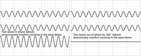
Constructive interference and destructive interference.
Image credit: H.M. Doss
The diagrams above combine waves of the same amplitude and wavelength. Waves may very well have different amplitudes and/or wavelengths. Whenever adding waves such as these, one adds the vertical component of each wave for a given horizontal location to find the resultant vertical component.
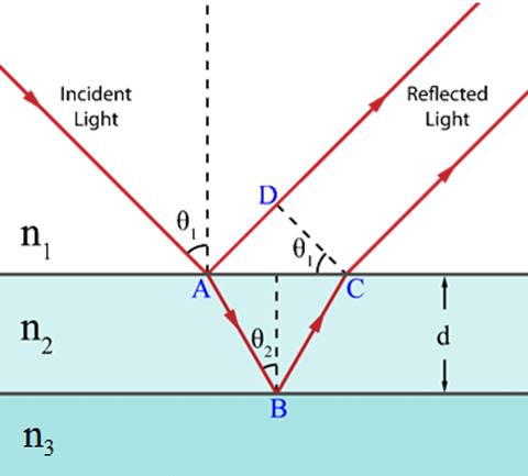
Image Credit: "Thin film interference1" by Chanli44 at English Wikipedia - Own work by the original uploader. This vector graphics image was created with Adobe Illustrator. Licensed under Public Domain via Wikimedia Commons
In the image above, the variable n refers to the index of refraction, which is the ratio of the speed of light in vacuum to the speed of light in that particular medium. When a photon strikes the interface between two media with different indices of refraction, it can split into two; part of its energy is reflected, while part is transmitted. In the diagram, the two reflected rays (one from the top surface and one from the bottom surface) have traveled different distances, and will be in different phases. When the medium beneath a reflection boundary has a higher index of refraction than the one above, the reflected ray undergoes a phase shift of 180˚ (think of sending a wave pulse down a rope that's tied to the wall; when it hits, it will "reflect" off and travel back down the rope, but inverted). But if the medium beneath a reflection boundary has a lower index of refraction than the one above, the reflection process doesn’t change the wave’s phase. Consider the distance the ray reflected from the bottom surface has traveled compared to the top reflected wave. If the incident light were head on (perpendicular to the surface) it would travel a distance of twice the thickness. With the incident ray at an angle, we can calculate the distance traveled:
and we can determine how the difference in distance shifts the phase of the wave! If the difference in distance traveled is equal to an integer number of wavelengths, then the phase shift due to the extra path length is zero. If the difference in distance traveled is an odd multiple of half the light’s wavelength, then the phase shift will be 180˚. (There is always the possibility that the two waves are somewhere between these conditions, and it is important to include the phase shifts from reflection as well.)
If sunlight is shining on a thin, transparent soap bubble, then only one wavelength of visible light will constructively interfere for a given thickness and viewing angle, causing this particular wavelength of light to have a greater reflected intensity then the others – this is the cause of the perpetually-shifting colors seen on soap films. To see different colors, all we need to do is observe reflected light that has traveled a different path length; this can be done by changing the viewing angle, the angle of the incident light, or the thickness of the film.
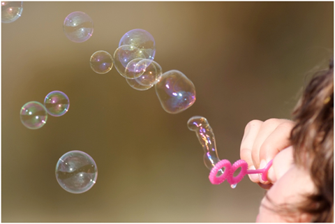
Image credit: "Girl blowing bubbles" by Taken byfir0002 | flagstaffotos.com.au Canon 20D + Canon 400mm f/5.6 L - Own work. Licensed under GFDL 1.2 via Wikimedia Commons
If alternating transparent thin films (with n2 > n1 > nair) are stacked in layers which have a thickness ¼ of the wavelength desired, they become a highly efficient reflector of that wavelength. This type of mirror is called a dielectric mirror (or a Bragg mirror) and can reflect a narrow range of wavelengths about the desired wavelength with an efficiency of greater than 99.99%. These types of mirrors are often used in lasers. By adjusting the thicknesses of the film layers, other unique optical properties can be attained: by increasing the film thickness every few layers to create something called a chirped mirror, the range of reflectance can be widened, and in the same way that a Bragg mirror utilizes constructive interference to achieve high reflectance, materials scientists have created antireflective surfaces, which cause destructive interference by ensuring that light from adjacent film layers are 180˚ out of phase with each other.
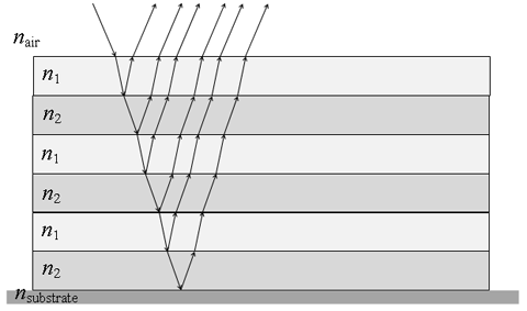
Diagram of a typical alternating thin film stack, which preferentially reflects a small range of wavelengths centered about a single wavelength. The thickness of the layers is proportional to the wavelength reflected (commonly ¼ wavelength). The remainder of the light is transmitted.
Image credit: H.M. Doss
The Berry and the Fiber
Thin film stacking is often found in nature, for example, in the beautiful margaritaria nobilis berry. One can see the berry in image (a) below. The other small inset shows a cross section through a single cell of the berry’s outer layers. This cross section shows a cylindrical structure. The large image in (a) shows a Scanning Electron Microscope (SEM) image of the layered structure within the cell. This structure is composed of concentric layers of thin films, whose thickness is such that it preferentially reflects blue light. Furthermore, because of the cylindrical shape of the stacking and the berry, it produces a high intensity of reflectance of this wavelength from many viewing angles.
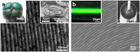
(a) Image of the margaritaria nobilis berry, a cross section of a single cell, and a SEM image of a portion of the cell’s cross section. (b) A tunable fiber preferentially reflecting green. A scanning micrograph of the layered fiber, and a SEM image of the transparent layers composing the fiber.
Image credit: Mathias Kolle
The scientists researching the berry came up with an idea of creating a fiber with the cylindrically layered alternating thin film structure. Image (b) above shows a fiber that is preferentially reflecting green light. The other small inset shows the rolled layers of two materials1: polydimethylsiloxane (PDMS, with nPDMS = 1.4 ± 0.02) and polyisoprene-polystyrene triblock copolymer (PSPI with nPSPI = 1.54 ± 0.02). Both of these materials are transparent to visible light, elastic, and inexpensive.
To fabricate the fiber the scientists use a glass (silicon) substrate that they put a thin layer of transparent PDMS atop (shown in green in the image below). Above the lower layer, a thin layer of transparent PSPI is placed. The transparent elastic layers are then rolled from the substrate onto a glass core fiber to create concentric layers of thin films, similar to those of the berry. This roll preferentially reflects a visible wavelength based on the thickness of the layers chosen (green in the fiber image above).
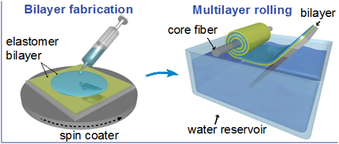
Fabrication of the tunable fiber. The bottom (green) layer is polydimethylsiloxane (PDMS, with nPDMS = 1.4 ± 0.02) and the top (blue) layer is polyisoprene-polystyrene triblock copolymer (PSPI with nPSPI = 1.54 ± 0.02). These are rolled onto a glass fiber. Later the glass can be etched away with chemicals.
Image credit: Mathias Kolle
Once the glass fiber core is removed by etching, the concentric layers of these transparent elastic polymers are free to be stretched. The stretching of the fiber changes the thickness of the layers, causing reflection of a different wavelength of light. The preferential reflected color of the unstretched fiber can be tuned to whatever wavelength is desired, and the range of wavelengths due to stretching can cover almost the entire visible spectrum.
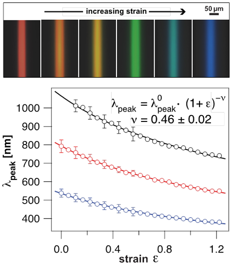
The top image shows the preferential color of reflection of the fiber as it is stretched. The bottom image shows three reflection peaks for the fiber as the strain (change in length divided by original length) is increased.
Image credit: Mathais Kolle
The fiber showed three peaks of reflectance, which shifted as the fiber was stretched. The unstretched fiber had a peak around 550 nm and two in the infrared region. As the fiber was incrementally stretched, the peaks shifted toward the blue region of the spectrum. The original green line shifted through the blues and eventually in the ultraviolet region. The middle peak, shown by the red line in the graph above, begins in the infrared region and ends in the green region as the fiber is stretched. The third peak shown by the top, black line nearly enters the visible red region.
Below is a link to the research group’s six minute video explaining their tunable fiber: Laboratory for Bio-inspired Photonic Engineering (LBPE)
Future Research and Applications
The researchers have already tried including asymmetric structures of chirality into the fibers to create patterns. They have wound the bilayer of films in a spiral on a plastic fiber core and observed a spiral pattern; they have also successfully rolled the bilayer onto a flexible core. By subjecting the fibers to thousands of stretch cycles, the long-term viability and optical performance of the fibers are being tested. Publication of this research should be sometime near the end of 2015.
Already, thoughts of utilizing the fibers for sports clothing that might show areas of stretching is being considered, along with the possibility of using the fibers as pressure sensors, for example in compression bandages. The scientists are also always looking for new interesting features in nature; recently they published a paper on a mollusc, the blue-rayed limpet, whose striking lines are created by a similar underlying structure.
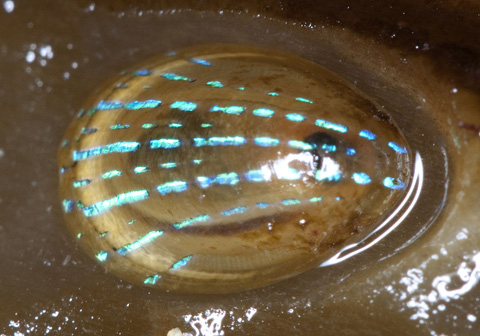
Image Credit: "Patella pellucida" by Andy.Cowley - Own work. Licensed under CC BY-SA 1.0 via Wikimedia Commons
References and Resources
1. Kolle, M., et al., Bio-Inspired Band-Gap Tunable Elastic Optical Multilayer Fibers, Adv. Mater. 25 2239-2245 (2013).2. Coffey, V., Where Life Meets Light: Bio-Inspired Photonics, Optics and Photonics News, April 2015.
3. Li, L., et al., A highly conspicuous mineralized composite photonic architecture in the translucent shell of the blue-rayed limpet, Nat. Commun. 6 6322 (2015).
* "Butterfly magnification series collage" by users SecretDisc, Shaddack, Michael Apel, and howcheng Licensed under CC BY-SA 3.0 via Wikimedia Commons - https://commons.wikimedia.org/wiki/File:Butterfly_magnification_series_collage.jpg#/media/File:Butterfly_magnification_series_collage.jpg
—H.M. Doss


