A Spin on Doppler
August 27, 2013
We have a number of devices to measure the speed of an object. We measure moving stars, galaxies, bugs, baseballs, and perhaps most commonly, vehicles caught in speed traps on the highway. Law enforcement uses Radar and LIDAR guns to measure our speed on the highway, but these devices make use of the same principle scientists use to measure how fast celestial objects move – the linear Doppler effect.
The Doppler effect can also help predict the weather and image fetuses in the womb. Recently, some attention has been given to the less popular angular Doppler effect used to measure rotational speed.
Lots of things rotate around an axis: planets, stars, galaxies, DVDs, baseballs, wheels, tops, tornadoes, atoms, and more. Being able to measure properties of rotation can provide insight into the structure of such objects, and research published in August 2013 has revealed some new twists on the rotational Doppler shift.
Linear Doppler Effect
The linear Doppler effect occurs whenever the source of a wave and the observer of that wave have some relative linear motion to each other. It's also important to note that there are slight differences when the source is moving toward the observer and when the observer is moving toward the source.
For example, a stationary person listening to the siren of an emergency vehicle will hear an increase in frequency as the siren approaches and a decrease in frequency as it passes by. This is because the sound waves emitted by the siren are emitted from points closer to the observer as the siren approaches, and from points further from the observer as the siren passes.
In this case, the observer detects no change in the speed of the wave. The observer detects a shorter wavelength and higher frequency on approach and longer a wavelength and smaller frequency as the siren passes.
A passenger on the moving vehicle would receive a steady wave front from the siren and would not detect any change in frequency.
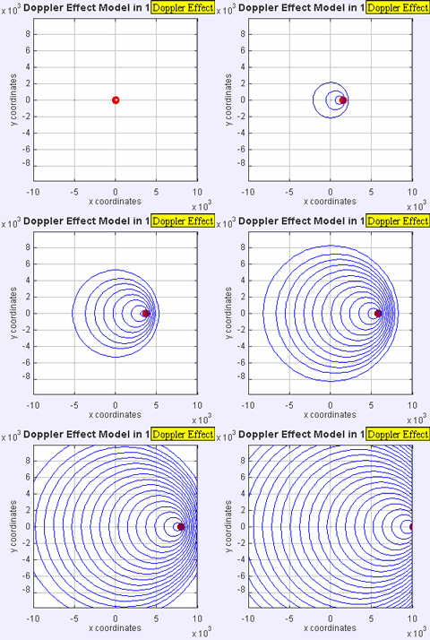
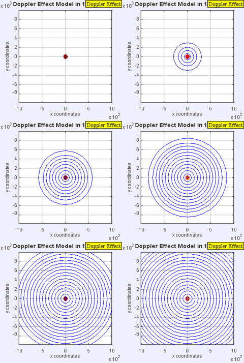
Left: This graphic shows what the Doppler effect looks like to an observer outside of a passing emergency vehicle with its siren blaring. Right: This graphic shows waves emitted by a stationary source.
Image credit: Lookang via Wikimedia Commons.
When the observer is moving and the source of the sound is stationary, then the distance between wavefronts emitted does not change. Instead, the observer travels through those wavefronts, and it appears to the observer that the wave is traveling at a higher speed, and with a higher frequency.
The moving observer detects wavefronts at a greater rate on approach (higher frequency), and at a smaller rate as the observer recedes from the source (lower frequency).
Here’s the equation describing the linear Doppler effect for waves not traveling too fast (much less than the speed of light):
where the top signs, plus in the numerator and minus in the denominator, are used for moving toward, and the bottom signs for moving away. This equation does not take into account movement of the medium.
If there is relative motion between a source interacting with a reflecting object (such as a wall), then the incident and reflected wave are frequency shifted, resulting in a higher frequency detected if the reflecting object is moving toward the detector, and lower if it is moving away.
The time it takes for the signal to reach the detector assists in imaging the surface that is reflecting the signal, and the frequency shift gives information on how that surface is moving. This is used to create ultrasonic images and give information of motion, and is used to image blood flow, muscle movement, and fetuses in utero.
The frequency of light appears higher (blue shifted) when an object is coming toward an observer and lower (red shifted) when it is moving away from an observer. Astronomers look at the spectrum of a star and determine the star’s actual brightness, and then measure its apparent brightness.
From comparing the apparent brightness and actual brightness they can determine how far away the star is. For galaxies, astronomers look for stars within the galaxy to estimate how far away a galaxy is. By measuring how the frequency of light is shifted astronomers can determine if a star is moving toward or away from us, and at what speed. Hubble showed with his measurements that there is a linear relationship with the distance and the amount of frequency shift.3 This relationship is called Hubble’s Law.
By knowing the brightness of a star one can calculate it's distance. From there, one can determine distances of further galaxies by measuring how their frequency is shifted and utilizing Hubble’s Law.
Light vs. Sound
Light waves differ from sound waves because they do not require any medium to travel through. Also, the speed of light serves as the upper speed limit for our present understanding of physics based on special relativity. For light, or any electromagnetic radiation, one cannot distinguish if the source is moving or if the observer is moving. This results in the following mathematical description:
where the plus sign is used for the source and observer approaching and the minus sign is used if they are receding. If the light is interacting with a reflective object, for example a moving mirror, then the frequency shift is doubled.
Here’s a video on the basics of the linear Doppler effect:
Note: The end of this video states that all galaxies are red shifted (moving away from each other). Most are but not all. For example the Andromeda galaxy is blue shifted (moving toward us) and is predicted to collide with our galaxy in four billion years.4
With a Twist
First it is important to note that if the light does not have some angular part to it, no angular frequency shift occurs. The angular part one usually considers comes from circular polarization of light, or any electromagnetic wave.
Light waves are made up of electric and magnetic fields that are perpendicular to each other and travel through space. If the electric and magnetic fields are rotating around the direction they are traveling in, then the light is circularly polarized. Linearly polarized light looks like the graphic of the electromagnetic wave below.
Light reflected off of water or glass is partially linearly polarized, or fully polarized at a specific angle (called the Brewster angle). Polarized sunglasses block the passage of one polarization (or orientation) of light and hence reduce the overall light reaching the eye.

An electromagnetic wave made of an electric field E and magnetic field B, that moves in the direction k.
Image credit: SuperManu, Wikimedia Commons
The angular or rotational Doppler shift has been around for a while. In reference 2, there is a derivation of the angular Doppler frequency shift. A comparison of the linear and angular Doppler effect on light sources is provided in the table below, adapted from reference 2.

For example, if the source of light is rotating, the observed frequency is shifted by the frequency of rotation, or ±f_rotation. When circularly polarized light reflects off of a rotating mirror, its frequency is shifted by ±2f_rotation. If the light is not circularly polarized then there is no frequency shift observed, in these descriptions.
New Results
In August of 2013, a research team in Scotland published some interesting results involving the angular Doppler effect.1 Instead of using circularly polarized light, the researchers used light that traveled forward in a spiral or helix. A helical light wave carries angular information in how the light is distributed in space.5
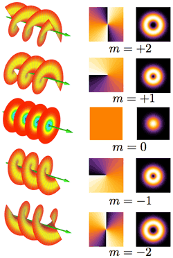
Helical light, phase fronts, and intensity distributions for different modes, m. Note that m = +1 spins one way, and m = -1 spins in the opposite direction, but both helical wave fronts travel in the same direction.
Image credit: E-karimi, Wikimedia Commons5
The mode m, indicates number of twists and the direction of the turn the light makes with the direction of propagation. For mode m = 0, the light is not a helix. It consists of circles that are not connected and is a form of a plane wave. For the mode m = +1, the light is a single helical surface that turns once around, counter clockwise when looking at it head on, over a single wavelength. The m = -1 mode turns once around in the clockwise direction, over a single wavelength. For m = ± 2, the light makes two helical surfaces per wavelength. To get an idea of this, follow the outer and inner helical paths in the images above for m = -1 and m = -2.
The scientists found that when the helical light interacted with a rough, rotating object, the observed frequency shift depended on the mode, m, of the helical light wave.
When the researchers used two helical beams of opposite modes (±m) shining on a rough, rotating object, an intensity modulation of frequency was observed, with the increased relative intensity (power per unit area) at a frequency of
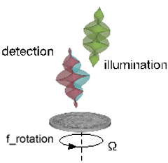
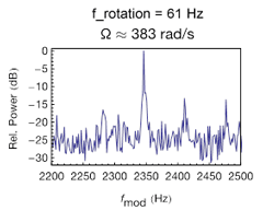 Left: Incoming beams of opposite helical modes (green) are scattered off of a rotating surface. The beam with negative mode m is red shifted, and the positive mode beam is blue shifted.
 Right: This results in an increased relative intensity at a Doppler shifted frequency dependent on the mode. The relative intensity is the relative power per unit area.
Image credit: Martin Lavery, University of Glasgow.
The rough surface means that the incoming light is reflected in many different directions and modes. The researchers used a rough surface to ensure that no matter what modes the light source contained, the scattered light would have a large range of modes.1 The scientists tested the equation for the intensity modulation of frequency with different modes, and found results supporting the equation above.
The scientists then reversed their experiment by interchanging the source and the detector, and were able to obtain experimental evidence again supporting the relationship for the frequency modulation equation.1
Based on their results, the researchers showed that they can infer the frequency of rotation of a distant object by considering the intensity modulation of the frequency detected.1
What's Next?
Two areas of application that the scientists mention in their article are remote sensing of turbulence in backscattered light and remote detection of rotating celestial bodies, for example the rotation rate of a planet outside our solar system.1
References and Resources
1. Lavery, M.P.J., et al., Detection of a Spinning Object Using Light’s Orbital Angular Momentum, Science 341, 537-540 (2013).https://www.sciencemag.org/content/341/6145/537.short?related-urls=yes&legid=sci;341/6145/537
2. Garetz, B.A., Angular Doppler effect, J. Opt. Soc. Am. 71 (5), 609-611 (1981).
http://www.opticsinfobase.org/josa/abstract.cfm?uri=josa-71-5-609
3. Scientific American, Ask the Experts (Jay M. Pasachoff), 21 October 1999.
http://www.scientificamerican.com/article.cfm?id=how-do-astronomers-measur
4. Doss, H.M. , Router Vision, APS, Physics Central
http://physicscentral.com/explore/action/router-vision.cfm
5. Orbital Angular Momentum of Light, Wikipedia
http://en.wikipedia.org/wiki/Orbital_angular_momentum_of_light
—Heide Doss


