Wirelessly Charged Electric Buses
In 2013, the University of Utah will have a bus route equipped with an electric bus that never needs to get plugged in!1-4 The bus will charge its battery as it picks up and drops off passengers by interacting with a device embedded under the surface of the road at the charging location. How? Using technology similar to that used to wirelessly charge an electric toothbrush, operators will be able to charge the buses while they wait at a stop.

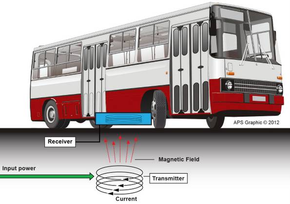
Figure 1. An electric bus charging wirelessly at a station. Image Credit: American Physical Society.
The wireless electric bus system
Researchers at Utah State University’s Energy Dynamics Laboratory and their collaborators designed this wireless charging technology and formed a spin-off company, WAVE: Wireless Advanced Vehicle Electrification.1-4 WAVE plans to demonstrate their technology on a new bus route at the University of Utah’s campus. An electric bus, equipped with a receiving device connected to its battery, will charge up while picking up and dropping off passengers at the charging location on the route. Each time the bus reaches the charging location, it will be over a transmitting pad for about five minutes.
The transmitting pad, which is embedded in the road, will be connected to the power grid. The interaction between the devices will charge the bus’ battery with an extremely high efficiency: About 98 percent of the energy transmitted will be received by the secondary pad on the bus! And the overall efficiency of the system from grid to bus is approximately 90 percent, according to James May, Vice President at WAVE.
Although this system is connected to the grid, it doesn’t need to be. Solar panels or other renewable energy sources can also be used to charge the electric bus. At the end of the day, operators can either continue to charge the bus wirelessly or plug it into an outlet. Ideally, charging could all be done wirelessly at the single embedded charging location without the need for a fueling station. The fundamental physics behind this technology isn’t new,5 but various research groups have tweaked and refined it for this application.
Charging an electric vehicle
WiTricity,6 a leading developer of wireless charging, has created a system that allows one to charge their electric vehicle while it is parked in their garage. The source coil, in a pad on the garage floor or embedded under the floor, is connected to the grid. The receiving coil, located between 6 and 12 inches above the floor, is attached to the battery of the car. This system charges the car’s battery with over 95 percent efficiency between the source coil and the battery, and over 90 percent efficiency between the grid and the car battery. Already kits have been made available to car manufacturers.
You might not think that a foot is a far distance, but it is much greater than distances prior to this technology, and it certainly is not the greatest distance that can be used.
The physics behind charging at a distance

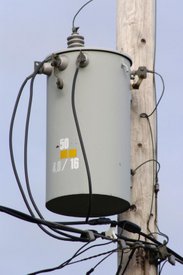
Figure 2: A common transformer. Image Credit: Glogger via WikiCommons.
This type of wireless charging relies on magnetic induction. Magnetic fields and electric fields act at a distance, and these fields interact with each other as well. Changing magnetic fields push or pull on charges, and if a charged particle moves it is called electric current. Similarly, moving charge (electric current) creates a magnetic field. When a changing magnetic field is near a closed loop of conducting wire, it will generate an electric current in the wire. In turn, the moving charges will produce another magnetic field. This bit of fundamental physics underlies motors, generators, transformers, and inductors.
Alternating currents (AC) are currents that change in time, and hence produce a magnetic field that changes in time. Consider a helical coil of wire (like a spring) with an alternating current in it. When brought near another coil of wire, the changing magnetic field of the first coil induces an electric current and magnetic field in the second coil. The coils of wire do not need to be touching each other, but the closer they are the larger the effect. This process is known as induction.
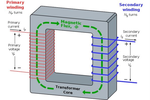
Transformers, like the one pictured to the right, rely on magnetic induction to increase or decrease voltage, among other tasks. Transformers on electric lines, for instance, are typically used to decrease the voltage supplied from power plants to residential areas. Transformers are also inside those large plugs that are used for cell phones, laptop computers, and printers.

Graphic of a transformer, showing coiled primary wire and coiled secondary wire. Often an iron core is placed in the windings to increase the amount of magnetic field lines that go through the secondary windings. Image credit: A. Daniels via WikiCommons.
An MIT physicist, Marin Soljačić,7-9 had the idea of adding resonance to these coils. Resonance involves the way an object naturally oscillates, such as in a swing. Pumping your feet at the correct time will allow you to swing higher by increasing the energy transferred to the swing. You also take advantage of electrical resonance when tuning to a particular radio station. Marin Soljačić made the two coils of the system highly resonant, which increases the efficiency of energy transfer and, most importantly, allows the energy to be transferred at considerable distances.8-9 Integrating the coil into an LC circuit, like those frequently found in radios, allowed Soljačić to achieve this.

Image Credit: Wolfmankurd via WikiCommons.
The coil acts as an inductor (L part of circuit), storing energy in its magnetic field as a current goes through the coiled wire. A capacitor (C part of circuit) completes the LC circuit. Capacitors are two conducting surfaces near each other that can charge up to a certain amount. Imagine a receiving coil that is experiencing an increasing magnetic field from the nearby source coil. This causes an electric current in the receiving coil’s wire. The charge moves along the wire until it reaches the capacitor and collects on one of the capacitor’s conducting surfaces.
As charge builds up on the capacitor, energy is stored in the electric field between its conducting surfaces. As the magnetic field from the source coil is reduced, the receiving coil tries to oppose the change, depleting the energy from its magnetic field and continuing the current. Eventually no energy is stored in the magnetic field of the inductor, and the current begins to flow the other way, reducing the charge on the capacitor and the energy stored in the electric field.
This current creates a magnetic field with opposite polarity (north and south poles switched) and increases the energy stored in the magnetic field of the coil again. A swinging back and forth between energy stored in the magnetic field of the inductor and the electric field of the capacitor occurs. This “swinging” of energy storage between the capacitor and inductor creates an oscillating circuit with a particular frequency.
Because the system is highly resonant, there is very little energy transferred to the outside environment, and the “swinging” continues for a long time with just a little push. Nonetheless, some energy is lost to the environment, so a certain amount of energy input is required to keep it going back and forth. The “kicking” input of this swing stems from the source coil that is connected to the grid. If a number of these resonant coils were placed around a large area, all the coils would oscillate at the same frequency, and they would not interact with coils tuned to different frequencies.6
A receiving coil can supply energy to an electronic device if it is properly fitted to it. This involves a little bit of circuitry and consideration of the geometry of the device to optimize the energy transferred. These systems can induce a current in one or more receiving resonant coils that are within range of the field generated by the resonant source coil.
The distance at which the coils can exchange energy depends heavily on the size of the coils—larger coils create a magnetic field that extends over a larger volume than smaller coils. According to WiTricity,6 coils that are 60 cm in diameter have been shown to transfer energy at over 98 percent efficiency when operated within a few centimeters of each other, and over 50 percent when operated at a 2 meter distance. However, high energy efficiency is still possible over long distances if resonant coils not hooked up to the grid (repeater coils) are placed between the source and final receiving device. These repeater coils transfer the energy if they are placed (in any direction) between the source coil and the receiving devices. This is similar to having cell towers in various locations that receive and retransmit electromagnetic signals to get cell phone coverage across large areas—except without the extra energy needed to amplify the signal! This highly resonant coupling makes this technique of energy transfer different from the traditional magnetic induction used in transformers.
With this idea, Marin Soljačić7-9 began a company called WiTricity.6 Watch the ten minute TED talk (linked below) for some cool displays (including lighting a light bulb across a room), and visit WiTricity’s YouTube site for other interesting videos on applications of this device.
WAVE, the company behind the wirelessly charged buses, has a website4 that describes the use of specially selected materials for their system. They use ferrite, a solid substance with magnetic properties, to shape and optimize the magnetic field and the energy transferred from one coil to another. They also use litz wires, which are insulated copper wires, braided or woven in a special way, to reduce how the wires affect each other. Both of these materials are used to reduce losses in the system. WiTricity6 uses different types of copper wires depending on which frequency they are interested in. Usually, the megahertz range calls for regular copper wire whereas litz wire is used for the kilohertz range.
Magnetic fields and humans
Although Earth’s magnetic field may go unnoticed in our daily lives, magnetic fields can certainly affect organisms. A static field acts differently from an oscillating field, and the strength of the field matters. However, magnetic fields are generally safe. Humans place their bodies in strong magnetic fields when they have an MRI (Magnetic Resonance Imaging) done. MRIs temporarily affect how certain molecules in the body point or move. Certainly, magnetic fields are considered to be less disruptive to organisms than electric fields. WiTricity has stated that the effects on humans of the oscillating fields produced by their technology are a hundred times less than the effects produced by cell phones,6 and that the fields are well below the limits set by the Federal Communications Commission (FCC), the International Electrical and Electronics Engineer Standards Association (IEEE-SA), and the International Commission on Non-Ionizing Radiation Protection (ICNIRP).
But current research has some people questioning our understanding of the affect of magnetic fields on organisms. Listen to this Physics Central podcast,10 which discusses various organisms and their internal magnetic compasses that respond to Earth’s static magnetic field. Even so, it may be that any affect that weak, oscillating magnetic fields have on organisms are less of a problem than the environmental damage from producing, transporting, and throwing away billions of batteries each year. Certainly the cost per kilowatt-hour of energy for these wirelessly powered devices is over 300 times less expensive than buying electricity in the form of a disposable batteries.6
Current and Future Research and Development
Research on improving the circuitry that hooks up to the battery of a device is underway. Current improvements in design focus on the geometries of devices. The most interesting area may be the development of a completely wireless environment. Imagine electronic subways, railways, and buildings that only use wirelessly charged devices. Use this link to see how a room in a future building could work.
Researchers are working on creating more flexibility and security over the frequency used by such devices.6 Imagine a conference room with one set of devices being powered by one source frequency, and another set of devices powered by a different source frequency, or the source itself might have a tunable frequency to allow someone to tune into different devices. This could also provide security for a system, allowing the ability to have an authentication with the source.
Scientists are also developing receivers or resonators that fit inside cases shaped like batteries.6 If fully developed, this technology would allow battery-operated devices to work within receiving limits without any need for batteries at all, just a battery shaped device.
In the near future, WiTricity will introduce Prodigy, a low cost wireless power system for demonstrations. Prodigy is intended for engineers, researchers, and educators to get hands-on experience with highly resonant wireless power transfer technology.6
References and Links
1.Hollenhorst, J, "Electric bus charges wirelessly at U of U", KSL.com Utah,16 November 2011
http://www.ksl.com/?nid=148&sid=18116082
2. Maffly, B, "U. of Utah shuttle system getting wireless electric bus", The Salt Lake Tribune, 18 June 2012 http://www.sltrib.com/sltrib/news/54117488-78/bus-technology-electric-smith.html.csp
3. Ferris, D "Innovate: Electricity in the Air", Sierra, Sep/Oct 2012. http://www.sierraclub.org/sierra/201209/innovate-electric-cars/step1.aspx
4. Wireless Advanced Vehicle Electrification (WAVE) http://www.waveipt.com/about/
5. Pulling the Plug on Conventional Charging, Physics Central, 2010 http://www.physicscentral.com/explore/action/inductivecharging1.cfm
6. WiTricity http://www.witricity.com/
7. Marin Soljačić, MIT Physics Department http://web.mit.edu/physics/people/faculty/soljacic_marin.html
8. Andre Kurs, Aristeidis Karalis, Robert Moffatt, J. D. Joannopoulos, Peter Fisher, Marin Soljačić, "Wireless Power Transfer via Strongly Coupled Magnetic Resonances", Science, Vol. 317. no. 5834, pp. 83 – 86, July 6, 2006 (Published Online June 7, 2007)
9. Aristeidis Karalis, J.D. Joannopoulos and Marin Soljačić, "Efficient wireless non-radiative mid-range energy transfer," Annals of Physics, Vol. 323, Issue 1, pp 34 – 48, April 27, 2007
10. Buzz Blog, Animals and their Compasses, Physics Central Podcast, 22 August 2012. http://www.physicscentral.com/buzz/blog/index.cfm?postid=8938525771276959665
- H.M. Doss


