Sonic Shock
About Shock Waves
Have you ever heard a sonic boom? Have you ever seen the shock waves that cause one? The first image shows shock waves from an F-18—a Navy jet—moving at supersonic speed. Shockwaves are regions of increased air pressure and temperature, and when these waves reach the ground, we hear the sonic boom. For another example, look at the “shadowgram” image of the speeding bullet. Here the first shock wave is curved and is actually slightly ahead of the bullet (it’s “detached”), and other shocks emanate from the bullet itself and even from the turbulent region of disturbed air directly behind.
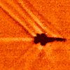
Shock waves from an F-18 in supersonic flight. (image courtesy of NASA).

A bullet moving faster than the speed of sound. In this kind of image, called a shadowgraph, the air within the shock waves, which has a different density from the surrounding air, bends light passing through to cast shadows on a screen (image courtesy of Andrew Davidhazy, Rochester Institute of Technology).
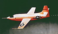
The rocket-powered Bell X-1, the first plane to break the sound barrier. (image courtesy of NASA)
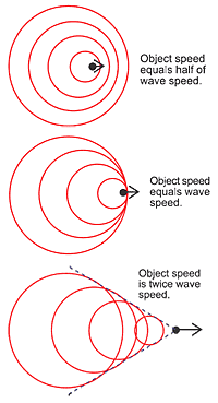
The drawings show waves produced at regular time intervals by an object moving through a fluid. When the object speed is less than the wave speed (top), the waves run out ahead. When the object speed equals the wave speed (middle), the waves pile up right in front of the object. When the object speed is greater than the wave speed (bottom), the waves form a wake.
To understand these shock waves, take a look at the diagrams below, which show waves spreading out from an object moving through a fluid. Such waves are produced continually as the object moves. Each diagram shows a series snapshots taken at regular time intervals. These waves spread out in circles, like ripples from a stone dropped into a pond, and move at the speed of the waves in the fluid. Notice that if the object moves faster than the speed of the waves, the circles form a “V”-shaped wake, like the wake of a ship or the shock waves from the nose of the F-18 in the image above.
As the diagram shows, when the object’s speed equals the wave speed, the waves pile up right in front of the object. In the 1940s, engineers feared that as an aircraft approached the speed of sound, this accumulation of waves could produce loss of control, and indeed, early attempts to break the sound barrier failed, with the loss of test aircraft and pilots. Finally, in 1947 Air Force pilot Chuck Yeager smoothly accelerated the Bell X-1 (see photo) to Mach 1.2, or 1.2 times the speed of sound, which at the X-1’s altitude is about 300 meters per second, (660 miles per hour).
Research
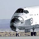
Blunt nose of the Space Shuttle (image courtesy of NASA)
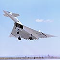
One of the two XB-70 bomber prototypes. The dark lines under the wings, near the wingtips, indicate the places where the wingtips fold down so the aircraft assumes an efficient shape for riding its shock wave. (image courtesy of NASA)

This photo shows the eight-foot-long prototype LoFLYTE, a test vehicle for the Waverider concept. LoFLYTE, which first flew in 1997, has a wing designed to ride on top of its own shockwave. (photo courtesy of ASTRA, which can be reached at info@astra.org.uk)
Unlike the needle-nosed Bell X-1, spacecraft reentry vehicles are blunt, like the nose of the Space Shuttle, shown in the photo. To understand how this design evolved, look at the shadowgrams of shock waves from various models of the reentry capsule for the first US manned spacecraft, Mercury, which first reached Earth orbit in 1962. Comparing the first image to the others shows that the shock wave detaches from a blunt body.
In the manned capsule concept, the larger radius of curvature—that is, the more smoothly rounded nose—reduces the rate of heat transfer from the hot shock wave to the vehicle surface, so the capsule can survive the fierce heating of reentry. Also, the blunt shape increases air resistance, slowing the reentering capsule at higher altitudes, where the lower air density produces a correspondingly lower rate of heating.
A blunt body is not, however, the only possible way to get back from space. A quite different approach, called “Waverider,” is basically a sharp-edged flying delta wing, conceived in Scotland in the 1950s. Gliding at several times the speed of sound, this vehicle would ride on its own shock wave, which would provide high lift with low drag. The Air Force XB-70 (see photo) was the first Waverider, but only two were built, and one of these crashed. This aircraft had wing tips that folded down to capture the shockwave underneath the wing and provide additional lift. A more recent Waverider prototype is a joint NASA-US Air Force project, LoFLYTE, an eight-foot-long, computer-controlled prototype (see photo).
The study of shock waves provides valuable information about the fundamental physics of fluids and also leads to important applications in the design of spacecraft and aircraft. Many physicists work on fluids, both in private industry and in departments of physics and aerospace/mechanical engineering in universities.

These shadowgraphs show shock waves from a series of models for the project Mercury reentry vehicle. Note how the rounded shapes detach the shock wave. (images courtesy of NASA)
Links
SILTEC
- Generation of Shock Waves by moving body: Animation
National Taiwan Normal University
- Moving Point Source: Interactive Animation
Kettering University
Scientific American Online
NOVA
Automatic Automation Corporation
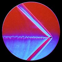
Schlieren image of the shock wave and turbulent wake of a bullet. Such images typically are made in a laboratory, but the image of the F-18 shown in About Shock Waves is also a Schlieren. (image courtesy of Andrew Davidhazy, Rochester Institute of Technology).


